This manual is the detailed technical reference for the project. It is the engineering datasheet: architecture, interfaces, programming model, verification, implementation, performance, and known limitations.
The repository root README.md remains the concise project overview. Normative
day-to-day sources such as docs/spec.md, docs/status.md, and docs/adr/
stay where they are; this manual summarizes stable structure and points at
those files by path instead of duplicating them.
1. How to use this manual
Chapters are assembled from individual files so they are easy to add, delete,
rename, and reorder. Each include:: line below maps to one file in
docs/sections/. Delete a line to drop a chapter; duplicate and rename a
line to add one; reorder lines to reorder chapters. Numbering follows document
order automatically through :sectnums:.
Keep each chapter in its own file and use == for the chapter title.
Subsections use === (and ==== sparingly). Deeper levels stay out of the
sidebar because :toclevels: is 3.
|
2. Introduction
This chapter states what the system is, what it is not, and how the rest of the manual is organized. Keep it short: one page that tells a new engineer whether they are in the right place.
2.1. Purpose
Describe the system in two or three sentences. Name the problem it solves, the
environment it targets, and the maturity of the implementation. Link out to
the concise project overview in README.md and to day-to-day status tracking
(such as docs/status.md in this repository) by file path.
A second paragraph should state non-goals explicitly. What is deliberately out of scope? What should a reader not expect from this system?
2.2. Scope and audience
The intended reader is an engineer who will build on, integrate, or verify this system. Assume fluency with the relevant domain and no prior knowledge of this project. The manual demonstrates the writing primitives used throughout:
-
normal paragraphs like this one,
-
unordered lists like this one,
-
ordered lists, such as the chapter map below,
-
inline codefor names of files, signals, commands, and identifiers.-
Manual roadmap
-
Architecture — major blocks and their responsibilities.
-
Design — internal structure and data flow.
-
Interfaces — boundaries other systems touch.
-
Programming model — how to drive the system.
-
Verification — how correctness is established.
-
Implementation — how it is built and delivered.
-
Performance — measured behavior and budgets.
-
Known limitations — honest boundaries.
-
External links look like this: the Asciidoctor documentation describes every block used in this manual. Internal cross references look like this: Verification explains how the claims in Performance are tested.
| Notes highlight information a reader needs but might skip. Use them for context, not for corrective action. |
Tips describe a better way to do something the reader already intends to
do, such as building this manual with make docs.
|
3. Architecture
Describe the system as a small number of major blocks plus the paths between them. A reader should leave this chapter able to draw the system on a whiteboard from memory.
3.1. Overview
One paragraph per block: what it owns, what it does not own, and which invariants it upholds. Prefer ownership statements ("Block A owns …") over mechanism; mechanism belongs in Design.
The table below is the canonical block inventory. Keep it dense: one row per block, one responsibility clause per row.
| Block | Responsibility | Owns (state / artifacts) |
|---|---|---|
Frontend |
Accept inputs, reject malformed inputs with diagnostics |
Input representation, error codes |
Core |
Transform validated inputs into results |
Intermediate representations, invariants |
Backend |
Deliver results to each supported target |
Target-specific lowering, output artifacts |
| If a block does not fit one row, it is probably two blocks. Split it. |
3.2. Data flow
Describe the end-to-end path in order. Name each handoff and the artifact it carries. A minimal equivalent in code:
input -> validate -> transform -> lower -> outputEach arrow is a contract: document the artifact format at the arrow, not just the stage at either end. Where a stage can fail, name the failure signal here and defer the full taxonomy to Verification.
3.3. Control and configuration
How is the system told what to do? Enumerate the control inputs: command-line flags, configuration files, environment variables, or control registers. State defaults and state which settings are fail-closed (an invalid setting stops the system rather than degrading silently).
tool check <file>          # validate only, report diagnostics
tool run <file> --verify  # validate, verify, then execute
4. Design
This chapter explains how the architecture is realized internally: data structures, flow of information, and error behavior. It is written for the engineer who must modify the system, not just use it.
4.1. Pipeline stages
Describe each stage in pipeline order. For each stage, state its input contract, its output contract, and the invariant it preserves for downstream stages. The figure below shows the generic shape; replace it with the real block diagram for this system.
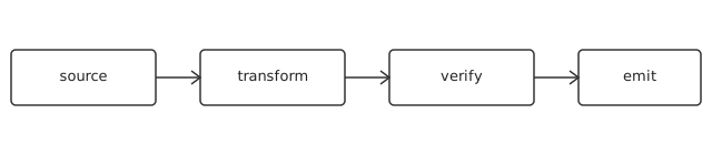
Keep figures simple line diagrams with a caption. Store sources next to the
manual (for example under docs/diagrams/) and export vector graphics into
docs/images/.
4.2. Representations
Name each intermediate representation or data model and the passes that may observe or mutate it. State explicitly what structure must be preserved across lowering: upstream stages must not destroy information that downstream stages (synthesis, optimization, code generation) still need.
| Document destructive normalizations here. Any pass that discards provenance, ordering, or precision must list exactly what it drops and which downstream consumer approved the loss. |
4.3. Error handling
Errors are part of the design, not an appendix to it. Classify every failure the system can report:
-
Input errors — malformed input, rejected before any transformation.
-
Verification errors — internally inconsistent state, fail closed.
-
Runtime traps — well-defined aborts with a code, never silent corruption.
Each class gets a code namespace that does not collide with the others, so a
bare code such as E110 or TRAP-REF is unambiguous without context.
5. Interfaces
Every boundary another engineer or system touches is specified here, in full. If it is not in this chapter, it is not an interface — change it freely. If it is in this chapter, changing it is a breaking change.
5.1. Conventions
State the rules that apply to every interface table in this chapter:
-
widths are in bits unless a
Unitcolumn says otherwise, -
directions are named from this system’s point of view (
In/Out), -
reserved fields are zero on write and ignored on read unless stated,
-
all multi-byte quantities state their byte order once, here.
| Byte order, reset values, and error signaling are the three interface details most often left implicit. This chapter leaves none of them implicit. |
5.2. Channels
One subsection per interface. The table is the contract; the prose explains only what the table cannot.
| Name | Width | Dir | Description |
|---|---|---|---|
|
1 |
In |
Strobe: the command word on |
|
32 |
In |
Command word; encoding defined in Programming model |
|
1 |
Out |
Strobe: |
|
32 |
Out |
Result word, or an error code from the error taxonomy |
A second interface follows the same pattern. Add subsections as needed; each appears as a collapsible entry in the sidebar.
6. Programming model
How to drive the system correctly. This chapter is read at a keyboard: every claim here should be executable or directly checkable.
6.1. Quick start
The smallest complete interaction, first. No explanation before the reader has seen it work:
tool check examples/hello        # validate, print diagnostics or "ok"
tool run   examples/hello        # execute from the entry point
Follow with one paragraph per line: what each command did, what success looks like, and where the corresponding diagnostics are specified (Error handling).
6.2. State and configuration map
Exhaustively list every knob and observable: registers, flags, configuration words, or API entry points. This is the table a driver author codes against.
| Name | Reset | Access | Description |
|---|---|---|---|
|
|
R/W |
|
|
|
R |
Bit |
|
|
R/W |
Mode word. Reserved bits must be written |
6.3. Sequences
Multi-step procedures as numbered lists, one step per action, with the expected observable after each step:
-
Write
CONFIG, then setCTRL_ENABLE=1. -
Poll
STATUSbit0until it clears. -
If
STATUSbit1is set, read back the result word: it holds an error code from the error taxonomy, not data.
6.3.1. Clearing a latched error
-
Write
CTRL_ENABLE=0to idle the unit. -
Read
STATUS: both bits must now be0. -
Re-write
CONFIGif the mode changed, then setCTRL_ENABLE=1again.
| Sequences that omit a stated step are unsupported, even if they appear to work. The system may enforce ordering in later revisions. |
7. Verification
How confidence in the system is established. Every normative claim elsewhere in this manual should be traceable to a check named here.
7.1. Strategy
One paragraph per layer, from cheapest to most expensive:
-
Unit checks — single blocks in isolation, including boundary values.
-
Negative checks — malformed inputs that must be rejected with the exact documented code, never a panic or silent acceptance.
-
Integration checks — end-to-end paths from input to observable output.
-
Differential checks — two independent implementations agreeing on outputs.
Document the fail-closed rule here: any verification stage that cannot prove its invariant stops the pipeline rather than passing suspect state through.
7.2. Coverage matrix
The matrix maps claims to evidence. Keep it current: a row without evidence is a roadmap item, not a fact.
| Claim (chapter) | Evidence | Location |
|---|---|---|
Input validation (Error handling) |
Corpus of malformed inputs, each mapped to its code |
Test suite / corpus directory |
End-to-end behavior (Quick start) |
Checked-in examples, all passing |
Examples directory |
Error taxonomy (Error handling) |
Snapshot tests over rendered diagnostics |
Test suite / snapshots |
Verification proves the checked-in tree, not the roadmap. Status
tracking (such as docs/status.md in this repository) records which rows are
backed by the working tree today.
|
8. Implementation
How the system is built, packaged, and delivered. A new contributor should be able to go from a clean checkout to a verified artifact by following this chapter alone.
8.1. Build
Prerequisites first: compilers, toolchains, and the minimum versions that are known to work. Then the build itself as a numbered sequence:
-
Fetch dependencies (one command; no manual downloads).
-
Build the artifacts (one command; state expected duration on a reference machine).
-
Run the verification gate from Regression policy.
tool fetch    # retrieve pinned dependencies
tool build    # produce artifacts under build/
tool gate # format, lint, and test — must pass before review| The build is reproducible: the same commit and the same pinned dependencies produce bit-identical artifacts. Anything that breaks reproducibility (timestamps, absolute paths, unpinned downloads) is a bug. |
8.2. Dependencies
Every dependency is load-bearing and listed here with its purpose. There is no vendored copy of anything the package manager can pin.
| Dependency | Version bound | Purpose |
|---|---|---|
Toolchain |
pinned per release |
Builds all artifacts; no alternative is supported |
Standard library only |
— |
Keeps the dependency surface auditable |
9. Performance
Measured behavior and resource budgets. Every number here names its method; numbers without methods live in marketing material, not in this manual.
9.1. Metrics
Report each metric with four columns: what was measured, on what, how, and the result. Point at the harness or benchmark definition rather than pasting raw logs.
| Metric | Setup | Method | Result |
|---|---|---|---|
Throughput |
Reference configuration |
Harness in |
record here |
Latency (p99) |
Reference configuration |
Same harness, same runs |
record here |
Footprint |
Smallest supported target |
Size of delivered artifact on disk |
record here |
9.2. Model
When performance follows a simple law, state it. The relationship below is shown as a literal block so the manual renders identically with or without mathematics support:
T = N / f      # wall time = work items / throughput
L = D + Q      # latency   = service demand + queueing
To render real equations instead, uncomment the :stem: attribute in
docs/index.adoc. That pulls MathJax from a CDN at page-view time, so it
remains opt-in: the default manual is fully self-contained.
| Budgets beat goals. Write each performance requirement as "at most X under conditions Y" and add the corresponding row to the coverage matrix. |
10. Known limitations
What the system does not do, cannot do, or does only under conditions. Write this chapter honestly: every limitation documented here is a support request that never gets filed.
-
Documented here and tracked — scheduled work with an owner.
-
Documented here and accepted — will not change; design around it.
-
Not documented anywhere — unknown, and therefore the reader’s risk. Keep this class empty by writing the other two down.
10.1. Accepted limitations
-
Scope boundary. Inputs outside the specified domain are rejected rather than handled. The exact rejection codes are listed in Error handling.
-
Scale boundary. Behavior above the validated limits in Performance is undefined; do not extrapolate the tables.
-
Platform boundary. Targets not named in Build are unsupported, even if the system appears to run on them.
| Accepted limitations are contractual. Later revisions may lift them, but no revision will silently violate them. If a limit changes, this chapter changes first. |
10.2. Near-term gaps
Numbered, each with its current workaround:
-
Gap one. What is missing, who is affected, and the supported workaround until it lands.
-
Gap two. Same pattern: missing capability, affected users, workaround.
When a gap closes, delete its item and move the new capability to the chapter that owns it. This chapter must never describe the present as if it were the future.