UDP Stack at a glance
100 Mbps UDP/IP stack in SystemVerilog on the Digilent Nexys A7-100T —
RMII PHY, MAC, IPv4, UDP, cut-through echo — the networking column so
itch can parse NASDAQ ITCH instead of wondering how bytes got off the cable.
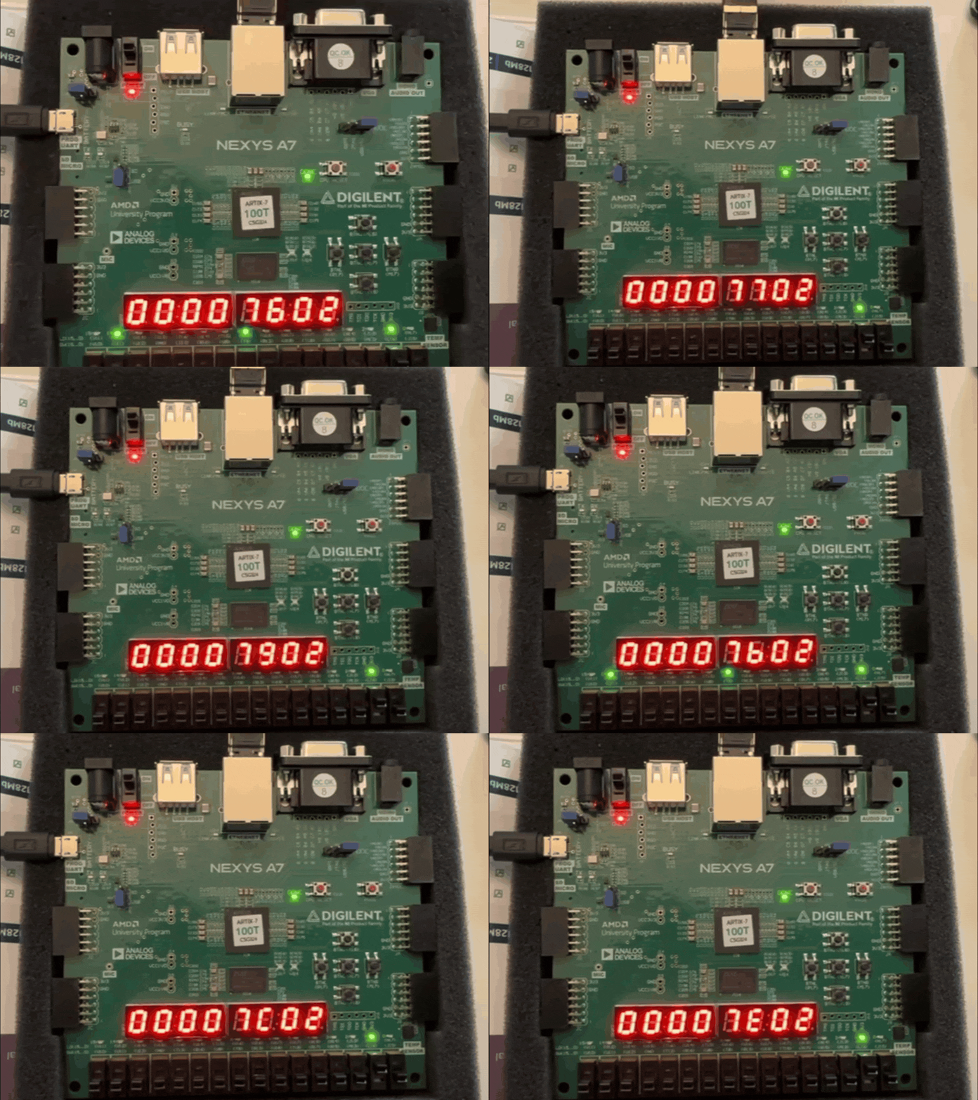
15 SystemVerilog files implement the full RX-to-TX path in logic.
Send a datagram to port 50000 and the FPGA returns it with 2-cycle latency.
| Measured fact (2026-08-10 build) | Value |
|---|---|
UDP payload echo ( |
2 cycles (20 ns) |
Timing @ 100 MHz |
WNS +1.985 ns, WHS +0.037 ns, 0 failing |
Fabric |
LUT 756 (1.19%), FF 599 (0.47%), IO 52 (24.8%), 0.115 W |
About this manual
This is the detailed engineering reference for the project.
It is the companion to the concise, GitHub-facing README.md:
-
README.md— project identity, status, quick start, bench photos. -
docs/(this manual) — architecture, interfaces, bring-up, verification, and implementation detail in engineering-manual style. -
log/— design journal with the TCP-vs-UDP argument. -
tmarhguy.com/writing— public essays behind the build.
Conventions used throughout:
-
monospacemarks commands, file paths, identifiers, and literals. -
File paths are repository-relative, e.g.
core/rtl/top.sv. -
Measured numbers cite their report or log source. Unmeasured values are
TBD (unmeasured)— never silently estimated. -
Normative Markdown (
docs/*.md,core/README.md,log/) is linked, not duplicated. This manual summarizes; the source file is truth.
Start with Introduction for scope and reading order,
then Architecture for the system overview.
The sidebar on the left is collapsible and searchable (press /).
|
1. Introduction
This chapter defines what the system is, what this manual covers, and how to navigate the rest of the document.
1.1. Purpose
NASDAQ’s Mold-wrapped ITCH feed rides on UDP multicast. Before any parser sees a byte, the FPGA needs a wire-to-payload path: bring up the LAN8720 PHY over RMII, strip Ethernet framing, demux IPv4, parse IP and UDP, and hand payload bytes to application logic.
This repo is that networking column — RMII PHY, MAC, IPv4, UDP, cut-through echo — so itch can worry about messages instead of wondering how bytes got off the cable. The design is 15 SystemVerilog files of dedicated logic covering the full RX-to-TX path.
Today the proof point is a UDP echo: send a datagram from the host, get it back on silicon with deterministic latency. Tomorrow the same MAC → IP → UDP spine plugs into `itch’s Mold unwrap — same RJ45, different payload handler.
The fastest way to see what the system is: the bench GIF at the top of this manual, and the loop in Architecture.
1.2. Scope
The manual covers:
-
datapath and module hierarchy (see Architecture)
-
per-layer behavior, clocks, and lab defaults (see Design)
-
lab addresses, tools, LEDs, and 7-segment map (see Interfaces)
-
Vivado build and bench bring-up (see Bring-Up)
-
simulation and correctness gates (see Verification)
-
post-route timing, utilization, and power (see Implementation)
-
honest limits and roadmap to
itch(see Known Limitations) -
design journal, essays, and companion repos (see Journal and References)
It does not replace:
-
README.md— project identity, quick start, bench photos -
docs/architecture.md,docs/metrics.md,docs/board_setup.md,docs/bitstream.md— normative short references (linked, not duplicated) -
core/README.md— Vivado GUI walkthrough -
log/— full design journal text -
Vivado reports under
core/core.runs/impl_1/— measurement sources
1.3. How to read this manual
Read chapters in order the first time. Chapters 1–2 give context; chapters 3–5 give the working model and bench use; chapters 6–7 give the evidence the stack behaves as claimed.
Each chapter is self-contained enough to be entered directly from the sidebar once the overview in Architecture is familiar.
1.4. Conventions
-
Internal references look like this: Verification.
-
External links look like this: Understanding UDP & ITCH, the public version of the TCP-vs-UDP argument.
-
Inline code uses monospace, e.g.
top.sv,udp_stack_core,50000,192.168.1.10. -
File paths are repository-relative, e.g.
core/rtl/stack/stack_tx.sv.
-
Unordered lists state properties or inventories.
-
Ordered lists state procedures where sequence matters:
-
Program the bitstream.
-
Plug Ethernet and check link LEDs.
-
Send UDP and watch RX/TX pulse.
-
Honest status is a project rule. Roadmap items stay labelled
roadmap; unverified claims stay out of this manual. Where a number has
not been measured it is written TBD (unmeasured).
|
The sidebar on the left is collapsible. Select a chapter title to
navigate; select its arrow control to expand or collapse subsections.
Press / to search this manual.
|
2. Architecture
System overview: what the pieces are, how packets flow in and back out, and where each piece lives in the tree.
2.1. The loop
Every lab session runs the same story. The full RX-to-TX arc runs on one FPGA.
  HOST IN              STACK                 HOST OUT
  ───────              ─────                 ────────
  UDP datagram    →    RMII RX → MAC    →    UDP reply
port 50000 IP → UDP → echo (swapped hdrs)-
Wire in. Live traffic hits the on-board LAN8720 PHY. RMII RX, IPv4 filter, UDP port match — payload bytes reach
loopback_echowithout a CPUmemcpy. -
Echo. Cut-through forwarding rebuilds Ethernet + IPv4 + UDP headers with swapped addresses. Latency instrumentation reports cycle count on
LED[12]. -
Wire out. Reply leaves through the same MAC and PHY.
LED[9]/LED[10]pulse on RX/TX;LED[13]/LED[15]show link up. The 7-segment and switch-mirrored LEDs tell you the bitstream is alive before you send a packet.
2.2. Datapath
RMII PHY ──► eth_mac_axis ──► eth_demux ──► ip_rx ──► udp_rx ──► loopback_echo
                                                                    │
                                                              stack_tx ◄──┘
                                                                    │
                                                         eth_mac_axis ──► RMII PHY
Inside udp_stack_core:
eth_demux → ip_rx → udp_rx → loopback_echo → axis_fifo → stack_tx| Role | Path |
|---|---|
Board top |
|
Stack core |
|
Sim top |
|
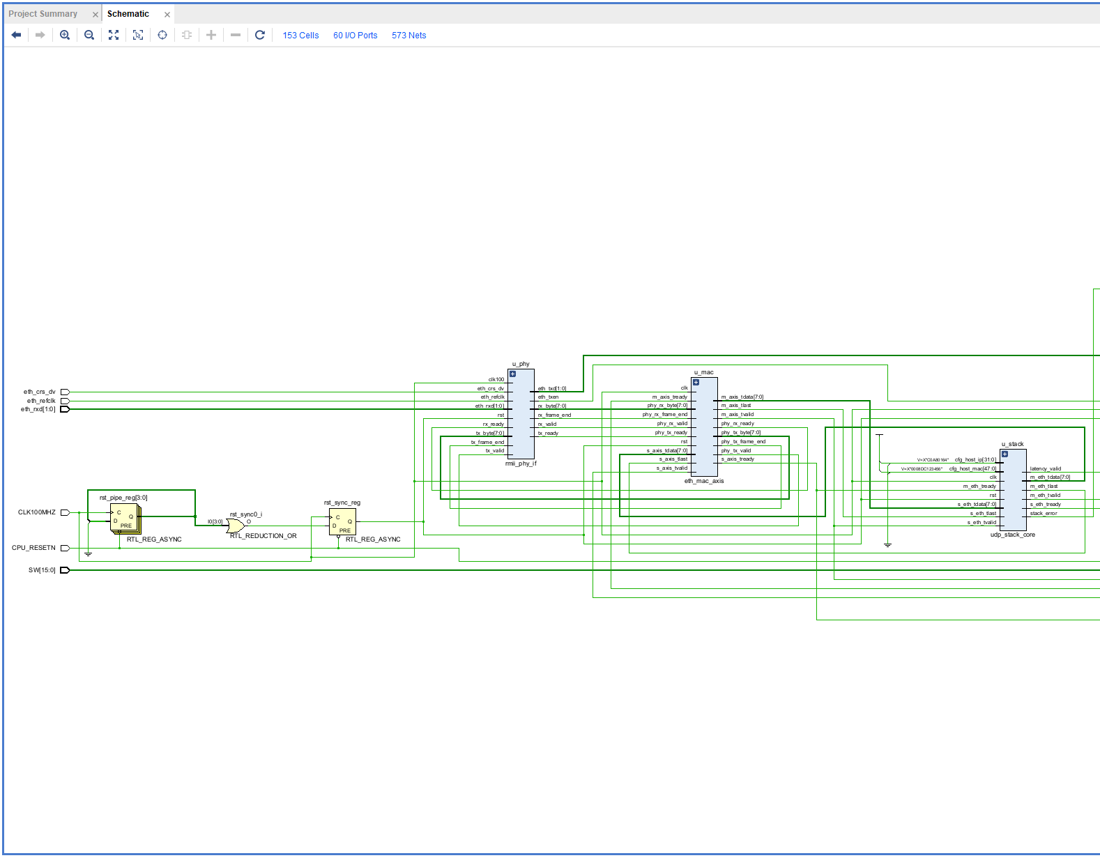
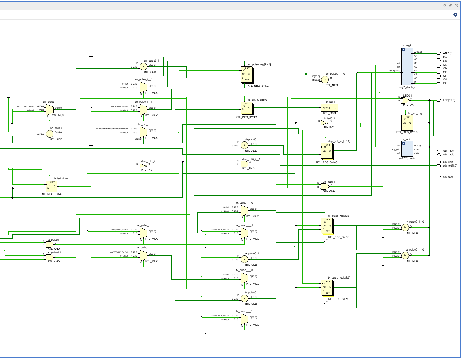
Synthesized hierarchy: top → u_mdio, u_phy, u_mac, u_stack, u_seg7.
2.3. Further reading
-
docs/architecture.md— datapath, modules, clocks (normative short form) -
core/rtl/top.sv— board wiring, LED and 7-segment assignments -
core/rtl/stack/udp_stack_core.sv— stack integration -
Design — per-layer behavior behind each box above
3. Design
Per-layer behavior, clocks, FIFOs, and lab defaults. This is the conceptual companion to the pin-level detail in Interfaces and the build evidence in Implementation.
3.1. Layer modules
| Layer | Module | Role |
|---|---|---|
PHY |
|
RMII 2-bit nibble stream at 50 MHz ref; MDIO link-status poll, |
L2 |
|
Preamble ( |
L2 demux |
|
IPv4 forward by EtherType |
L3 |
|
20-byte IPv4 header parse, protocol |
L4 |
|
8-byte UDP header parse, dst-port |
App |
|
Cut-through payload pass ( |
TX |
|
42-byte Ethernet (14) + IPv4 (20) + UDP (8) header rebuild with swapped src/dst, then payload stream |
ARP |
|
Single-entry stub; lab uses pre-seeded |
Common |
|
Payload elasticity, RMII 50 MHz ↔ 100 MHz crossing, FCS, heartbeat display |
Source tree: core/rtl/{phy,mac,arp,ip,udp,stack,common}/ — 15 .sv files total.
3.2. RX behavior
-
MAC
RxIdle → RxPre → RxData: wait for0x55, expect0xD5SFD, then stream bytes tom_axis.phy_rx_frame_endterminates the frame. -
eth_demuxforwards only IPv4; ARP is flagged, not answered in lab. -
ip_rxstatesStHdr → StFwd / StDrop: captures protocol, src/dst IP across bytes 9–19; assertsm_meta_validonly onproto == 17and dst-IP match, elseip_errorand drop. -
udp_rxstatesStHdr → StPay / StDrop: captures src/dst ports across bytes 0–3; assertsm_meta_validonly on dst-port50000, elseudp_errorand drop. -
loopback_echois combinational pass-through for data with sidecar counters:armedon firstvalid && ready,latency_cycles = cycle_cnt - start_cyclepulsed on last beat.LED[12]mirrorslatency_valid.
3.3. TX behavior
stack_tx states StIdle → StHdr → StPay:
-
pkt_start(raised byudp_stack_coreafter payload length is known) latchescfg_udp_len,cfg_dst_mac/ip/port. -
StHdremits 42 header bytes viahdr_byte(): dst MAC,LOCAL_MAC 00:0A:35:00:00:01, EtherType0x0800, IPv40x45…,proto 0x11, src192.168.1.10, dst = RX src IP, src port50000, dst = RX src port, UDP length, zero checksum. -
StPaydrainsaxis_fifopayload withtlastpreserved. -
MAC
TxIdle → TxIfg → TxPre → TxData → TxFcs: 12-byte IFG wait, 8-byte preamble, payload with runningeth_crc32, 4-byte FCS,phy_tx_frame_endon last CRC byte.
stack_error = ip_err | udp_err drives LED[11].
3.4. Clocks and crossing
| Clock | Source | Period |
|---|---|---|
|
Board oscillator (pin E3) |
10 ns (100 MHz) |
|
PHY RMII ref (pin D5) |
20 ns (50 MHz) |
core/constrs/nexys_a7_100t.xdc declares both clocks and
set_clock_groups -asynchronous between them — required for the
byte_cdc_fifo RMII crossing. top.sv adds a 4-stage reset synchronizer
off CPU_RESETN.
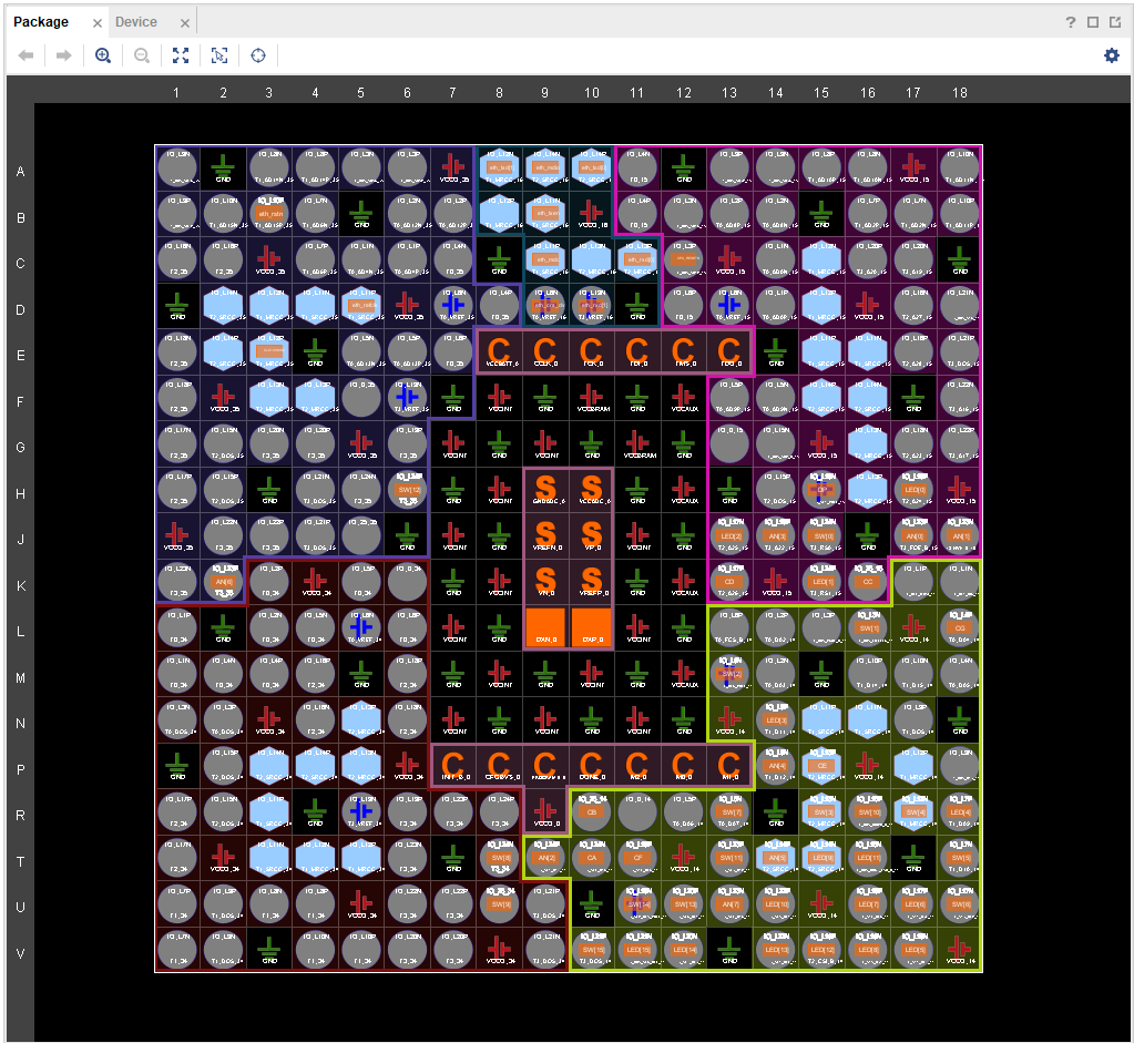
eth_rxd/txd/mdc/mdio pinned on xc7a100t3.5. Lab defaults
| Parameter | Value | Defined in |
|---|---|---|
FPGA IP |
|
|
FPGA MAC |
|
|
Host IP |
|
|
Host MAC |
|
|
UDP port |
|
|
Part |
|
Vivado project |
Broadcast (255.255.255.255) works for direct-cable tests without ARP.
See Interfaces for the tools that use these values.
4. Interfaces
How operators and scripts touch the system: lab addresses, host tools, LEDs, 7-segment, and pin constraints.
4.1. Network addresses
From core/rtl/top.sv and core/rtl/stack/udp_stack_core.sv:
| Field | Value |
|---|---|
FPGA IP |
|
Host IP |
|
UDP port |
|
Host MAC |
set |
Edit before building for a new host:
localparam logic [47:0] HOST_MAC = 48'h00_08_DC_12_34_56;
localparam logic [31:0] HOST_IP  = {8'd192, 8'd168, 8'd1, 8'd100};
4.2. Host tools
tools/send_udp.py — send a datagram and wait for the echo:
# Direct cable without ARP — broadcast works
python tools/send_udp.py --host 255.255.255.255 --port 50000

# Targeted echo with custom payload
python tools/send_udp.py --host 192.168.1.10 --port 50000 --payload "echo-test"

# Repeat N times
python tools/send_udp.py --host 192.168.1.10 --port 50000 --payload "bench" --repeat 10
tools/bench_check.py — wire-level sanity wrapper around the above
(--host 255.255.255.255 --payload bench):
python tools/bench_check.pyBoth use plain UDP sockets with SO_BROADCAST and a 2 s reply timeout.
No reply (timeout) means link, address, or bitstream needs checking —
see Bring-Up.
4.3. LEDs
From core/rtl/top.sv:
| LED | Meaning |
|---|---|
|
Mirror |
|
Heartbeat (~1 Hz, |
|
RX activity pulse (5 M-cycle stretch) |
|
TX activity pulse (5 M-cycle stretch) |
|
Stack error ( |
|
Latency-valid pulse ( |
|
PHY link up ( |
4.4. 7-segment display
Right to left on the board (from seg_value in top.sv):
-
Right 2 digits:
SW[7:0]in hex. -
Next 2 digits: heartbeat counter (slowly increments each blink).
-
Left 4 digits:
0000.
4.5. Pin constraints
core/constrs/nexys_a7_100t.xdc maps top ports to Nexys A7 pins:
| Constraint | Purpose |
|---|---|
|
100 MHz board clock, 10 ns |
|
50 MHz RMII ref, 20 ns |
|
unrelated clocks for CDC FIFO |
|
center-button reset path ( |
|
switches and status above |
|
7-segment cathodes and anodes |
|
RMII + MDIO to LAN8720 |
The XDC must stay paired with top. Port names match exactly
(CLK100MHZ, eth_refclk, LED[15:0]). constraints/udp_consts.xdc
is a legacy copy — core/constrs/nexys_a7_100t.xdc is the build truth.
|
5. Bring-Up
Program, cable, and traffic for the echo on the bench.
docs/board_setup.md is the normative short form; this chapter adds
the GUI flow and checklist in manual order.
5.1. Vivado project
| Item | Value |
|---|---|
Toolchain |
Vivado 2025.2 |
Project file |
|
Top module |
|
RTL |
|
Constraints |
|
Part |
|
Output |
|
GUI flow (full steps in core/README.md):
-
File → Project → New in
core/, RTL project, partxc7a100tcsg324-1. -
Add Sources → Add Directories →
core/rtl/(all 15 files stay checked). -
Set top: right-click
top.sv→ Set as Top. -
Add Constraints →
core/constrs/nexys_a7_100t.xdc. -
Run Synthesis → Implementation → Generate Bitstream.
5.2. Program and cable
-
Program bitstream:
core/core.runs/impl_1/top.bit. -
Connect RJ-45 to the FPGA Ethernet port, not a monitor passthrough.
-
Host on
192.168.1.x(192.168.1.100default) or use broadcast.
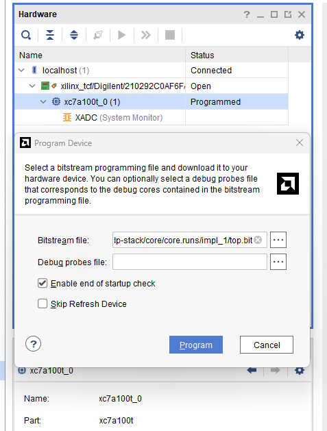
top.bit on xc7a100t_05.3. Traffic
python tools/send_udp.py --host 255.255.255.255 --port 50000
python tools/send_udp.py --host 192.168.1.10 --port 50000 --payload "echo-test"
python tools/bench_check.py
5.4. Bring-up checklist
-
Program bitstream → LED[8] blinks ~once per second.
-
Flip switches → LED[7:0] follow SW[7:0]; right 7-seg digits show hex.
-
Plug Ethernet → LED[13]/[15] on when link is up.
-
Send UDP → LED[9]/[10] pulse;
send_udp.pyprintsReply … bytes.
If segments stay pale, re-synthesize after confirming
rtl/common/seg7_display.sv is in Design Sources. If no reply, check
HOST_MAC, host subnet, and that the cable is in the FPGA jack.
Post-route evidence lives in Implementation.
|
6. Verification
How the project proves the stack is correct — and how to re-run that proof locally. Simulation comes first: the bitstream is trusted only after the loopback passes.
6.1. Testbench map
| Gate | Toplevel | Python driver |
|---|---|---|
loopback (default) |
|
|
udp |
|
|
ip |
|
|
arp |
|
|
mac |
|
|
HDL TBs live in sim/hdl/; packet helpers in sim/python/eth_packets.py;
runner in sim/cocotb/run_tests.py (Icarus by default, SIM overridable,
Windows-friendly with no GNU make).
6.2. Running the gates
cd sim/cocotb
pip install -r ../requirements.txt
python run_tests.py
Unit gates (same as CI):
cd sim/cocotb
TEST=udp python run_tests.py
TEST=ip  python run_tests.py
TEST=arp python run_tests.py
TEST=mac python run_tests.py
This is the same gate CI runs on every push (.github/workflows/ci.yml):
install Icarus + requirements, run loopback, run the four unit gates,
upload sim/results/latency_summary.json.
6.3. Correctness properties
| Property | Where it is checked |
|---|---|
UDP payload echo preserves bytes and |
loopback perf test |
IP drops non-UDP and wrong dst-IP with |
|
UDP drops wrong dst-port with |
|
ARP single-entry behavior |
|
MAC strips preamble, forwards frame, appends FCS |
|
stack_error = ip_err | udp_err is the single board-visible error
aggregate (see Interfaces).
6.4. Latency budget
Source: sim/results/latency_summary.json — written by
test_loopback_perf.
| Metric | Budget | Measured |
|---|---|---|
Payload loopback ( |
≤ 20 cycles (200 ns) |
2 cycles (20 ns) |
{
  "loopback_max_cycles": 2,
  "loopback_max_ns": 20
}
Regenerate with cd sim/cocotb && python run_tests.py.
Wire-level confirmation is LED[12] pulsing per packet on the bench.
| When adding a header feature, add the drop-path test first. A failing unit test is the specification; a passing one is the proof. |
7. Implementation
Vivado build flow and measured post-route behavior. Numbers below are copied from files in this repo — not estimated. Last Vivado build: 2026-08-10, Vivado 2025.2.
7.1. Reports
Reports: core/core.runs/impl_1/
-
Timing:
top_timing_summary_routed.rpt— Design Timing Summary. -
Utilization:
top_utilization_placed.rpt(post-place). -
Power:
top_power_routed.rpt.
Screenshots: media/proj_summary.png, media/dashboard.png,
media/impl_device_design.png, media/synth_design.png.
7.2. Timing @ 100 MHz
| Metric | Value |
|---|---|
WNS |
+1.985 ns |
TNS |
0.000 ns |
WHS |
+0.037 ns |
THS |
0.000 ns |
Failing endpoints |
0 |
Timing closed at 100 MHz with ~2 ns of setup slack.
7.3. Utilization — xc7a100tcsg324-1
| Resource | Used | Util% |
|---|---|---|
Slice LUTs |
756 |
1.19% |
Slice FFs |
599 |
0.47% |
Bonded IOB |
52 |
24.76% |
BUFG |
2 |
6.25% |
Vivado Project Summary rounds LUT/FF to 1% and IO to 25% — same build, coarser display. Light on fabric, heavy on I/O — exactly what a wire-facing stack should look like.
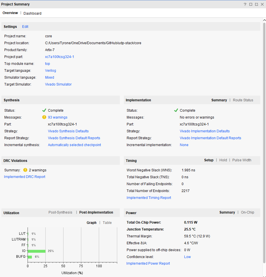
synth_1 / impl_1)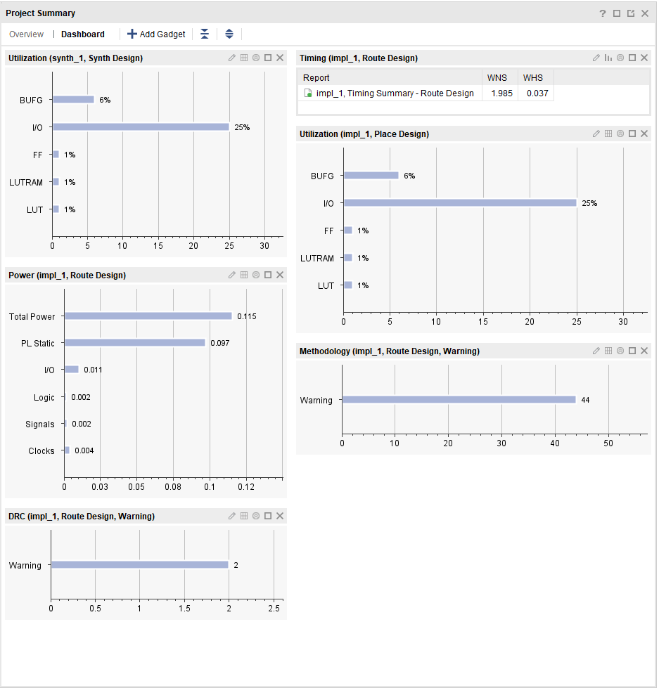
7.4. Power
Source: top_power_routed.rpt
| Rail | Value |
|---|---|
Total on-chip (est.) |
0.115 W |
Dynamic |
0.018 W |
Device static |
0.097 W |
Junction (est.) |
25.5 °C |
7.5. Floorplan
Post-route floorplan — logic placement on Artix-7 fabric (same 2026-08-10 build):
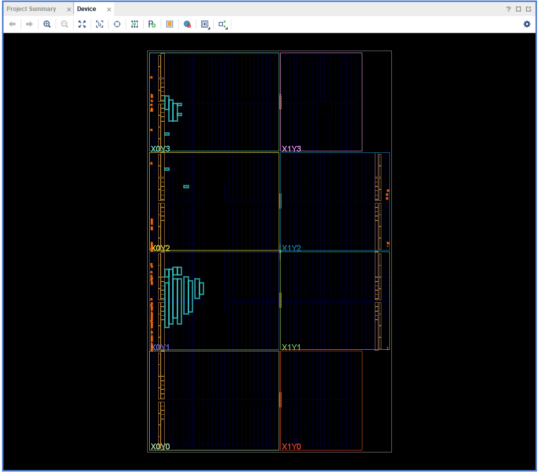
The stack concentrates in left clock regions; I/O banks sit at the
package edges. Package pinout (eth_rxd/txd/mdc/mdio) matches
top.sv and nexys_a7_100t.xdc — see Design.
kgCO₂ or latency numbers copied from another project do not
belong here. If it was not measured in this tree, it is
TBD (unmeasured).
|
8. Known Limitations
Honest boundaries: what the system is, and what it is not. This chapter overrides any optimistic reading of earlier chapters.
8.1. What is real today
-
RMII PHY + MDIO link detect (
link_uponLED[13]/[15], 50/100 MHz CDC). -
MAC RX preamble strip and TX preamble + FCS + IFG (
eth_mac_axis). -
IPv4 header parse with dst-IP filter (
ip_rx). -
UDP header parse with dst-port
50000filter (udp_rx). -
Cut-through payload echo with 2-cycle sim latency (
loopback_echo). -
Header rebuild with swapped src/dst (
stack_tx+axis_fifo). -
Vivado 2025.2 bitstream with closed timing (WNS +1.985 ns @ 100 MHz).
-
cocotb loopback + udp/ip/arp/mac gates in CI.
-
Bench tools
send_udp.py/bench_check.pywith broadcast support.
8.2. What is explicitly not here
-
ARP is a lab stub.
eth_demuxdetects ARP EtherType;arp_cacheis single-entry. Dynamic lookup is not wired — pre-seedHOST_MACintop.svor use255.255.255.255broadcast for direct-cable tests. -
ITCH parsing lives in
itch. Payload handling stops at echo here. Mold unwrap and order-book logic live in itch. -
UDP only. TCP, DHCP, and ICMP packets are dropped. Non-UDP IPv4 raises
ip_errorand is dropped by design. -
Checksums are minimal. TX IP/UDP checksums are zero-filled lab values; RX does not validate header checksums beyond structure and filter.
8.3. Limits to design around
-
A packet is echoed if and only if it is IPv4 + UDP + dst-IP match
dst-port50000; everything else is dropped withstack_errorpulsed. -
Published numbers are measured in this tree (2-cycle loopback, WNS +1.985 ns, 756 LUT / 599 FF / 0.115 W). Unmeasured values are
TBD (unmeasured). -
Same board, same PHY for
itch— different payload handler above UDP. Replaceloopback_echowith Mold/ITCH ingress; keep MAC → IP → UDP.
9. Journal and References
Design narrative, public essays, companion repos, and the doc map. The journal is the argument; this manual is the map.
9.1. Design journal
log/ holds the running lab record:
| Log | Topic |
|---|---|
|
Why UDP, TCP three-way-handshake cost, hardware advantage (FPGA ns vs PCIe/OS), multicast goal — the Wharton open-book origin |
Core argument in one table (from the log):
| Protocol | Priority | Analogy | Integrity |
|---|---|---|---|
TCP |
Reliability |
Downloading a file |
ordered, retransmitted, never drops — pauses on loss |
UDP |
Speed & recency |
Live video call |
drops stale frames, always pushes latest |
Exchanges push market data over UDP multicast: fire the newest update, drop anything stale, keep moving. Parsing ITCH in hardware puts the FPGA in the loop instead of kernel buffers and interrupts.
9.2. Writing (tmarhguy.com)
| Essay | Topic |
|---|---|
TCP vs UDP for market data, public version of the log |
|
Cable, link LED, end-to-end bench goal |
|
First clean Vivado run (Aug 02, |
9.3. Companion repos
-
NASDAQ ITCH hardware parser — consumes this stack’s payload stream.
-
itch-hw — earlier hardware parser reference from the log.
-
SeaLion and MAC unit — sister projects sharing this manual’s theme and layout.
9.4. Doc map
| Doc | What’s in it |
|---|---|
|
Documentation index (short form) |
|
Datapath, modules, clocks |
|
Cable, LEDs, host IP, traffic |
|
Timing, utilization, latency from reports |
|
Vivado build flow and output path |
|
Vivado GUI project setup |
|
Design journal |
Cite reports by filename (top_timing_summary_routed.rpt) and
screenshots by media/ path so any reader can re-derive the numbers in
Implementation.
|
10. Authors
The manual and the stack are produced by the author behind the design and the public build log.
10.1. Tyrone Marhguy
Computer Engineering '28, University of Pennsylvania.
Personal FPGA project: custom UDP/IP on Nexys A7, companion stack for
hardware ITCH parsing, and a public build log at tmarhguy.com.
Questions or collabs — reach out. See also projects and engineering log for Tomato, SeaLion, FramePort, and the ITCH series this stack supports.